For existing flame furnaces, regenerators play a significant role in recovering the energy contained in the exhaust fumes. Adequately designed regenerators can recover over 75% of the energy contained in the fumes, and provide up to 30% of the total energy needed to melt glass (Figure 1).
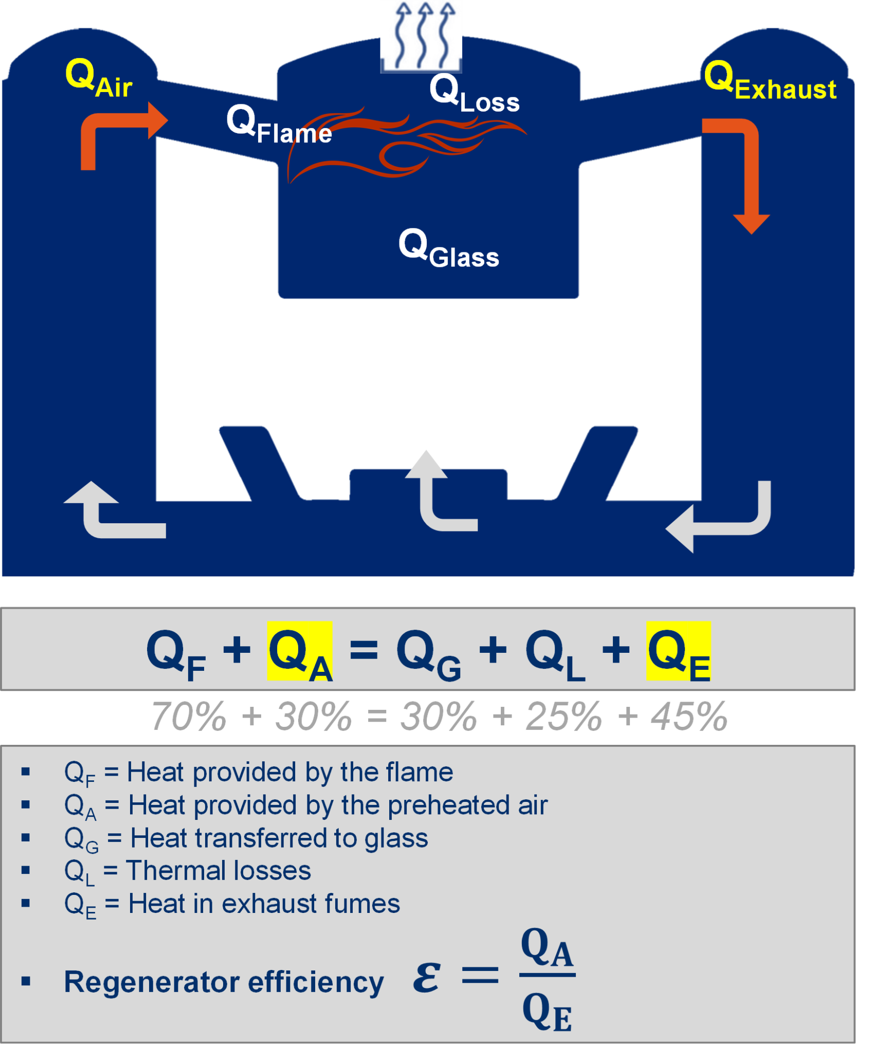
The efficiency of regenerators is driven by the capability of the packing to transfer heat (stored during the fumes phase of the cycle) to cold intake air during the air phase. For flame furnaces, the benefits of regenerators were demonstrated very quickly in the industrialization of glass manufacturing.
High thermal efficiency regenerator
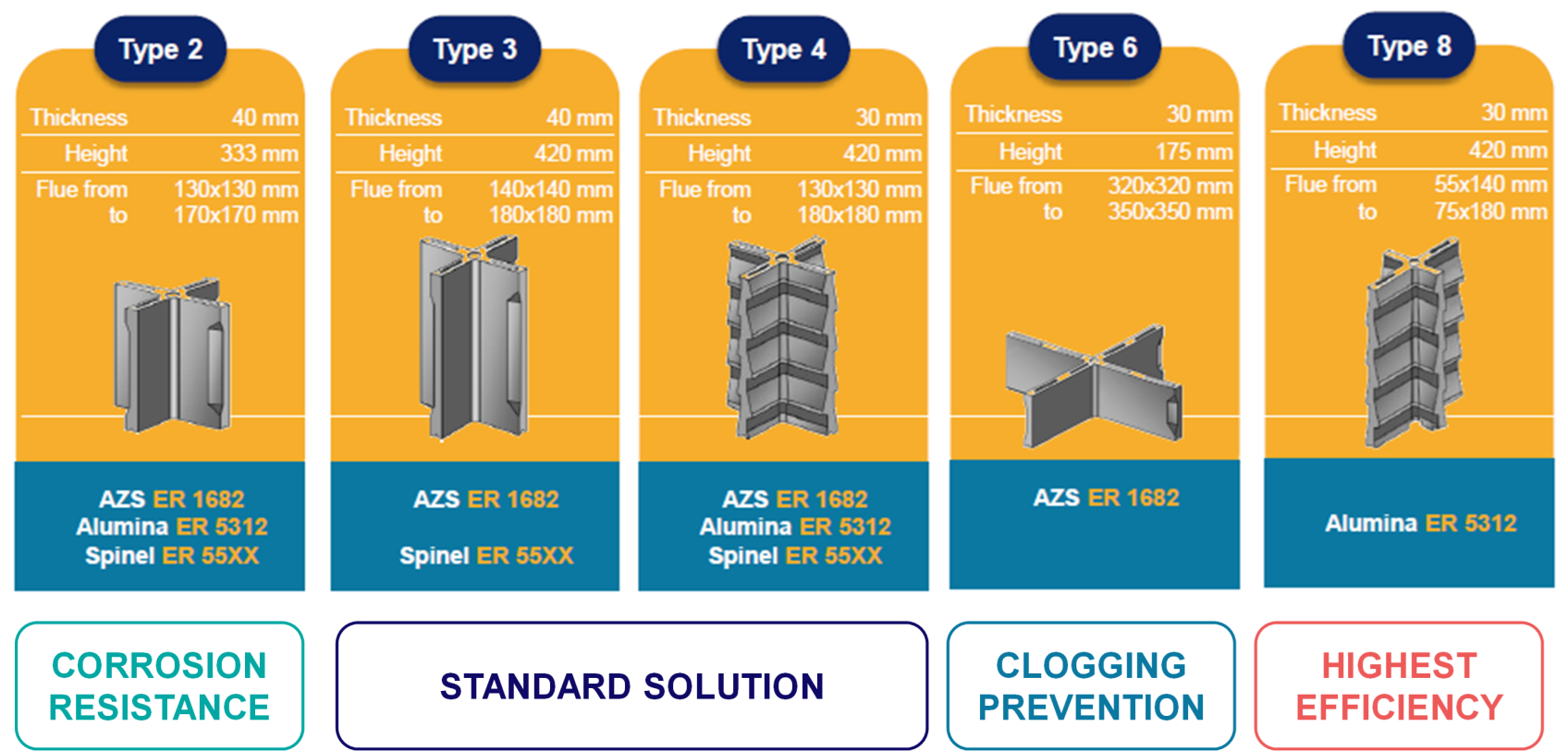
Over the last decades, with the support of numerical simulation and the use of an industrial experimental setup, SEFPRO studied the mechanisms driving heat transfer between refractory materials and fluids (air & fumes). The range of experimental conditions studied allowed to cover the different flow regimes that could exist inside the regenerators of a glass furnace. Combining in-depth study of literature, experimental results and refractory materials expertise, SEFPRO developed innovative CRUCIFORMS® solutions to improve the energy efficiency of glass furnaces. CRUCIFORMS® products are a unique fused-cast solution, combining different geometries (Figure 2) to design the regenerators with the highest thermal performance and optimized CAPEX (Figure 3).
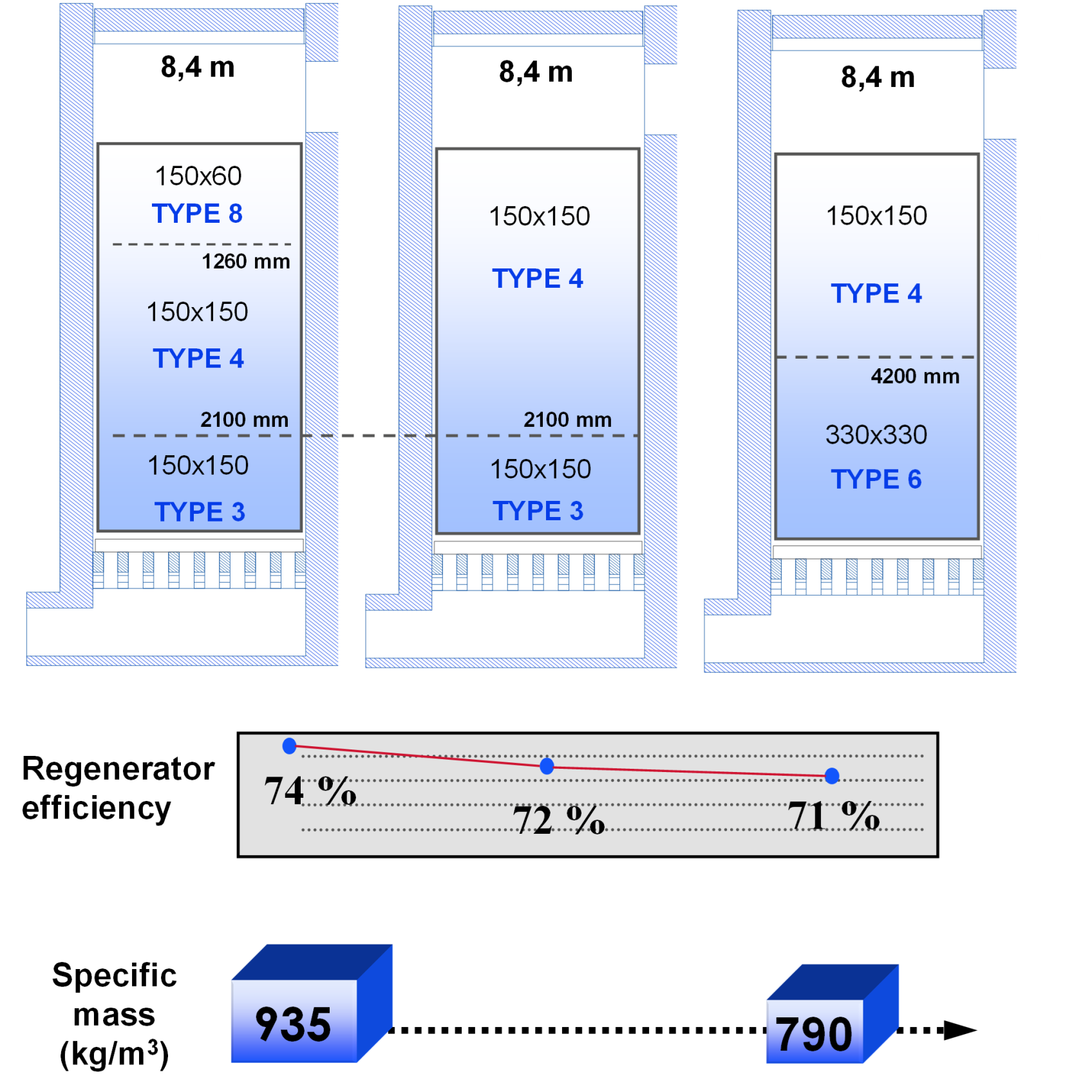
Moreover, the different fused-cast compositions available (AZS, β-alumina & alumina-magnesia spinel) offer the possibility to have refractory materials adapted to the local corrosion processes that vary along the height of the packing.
Clogging of regenerators and its effect on energy consumption
During operations, corrosion processes linked to fumes, carry-overs, vapors, and condensation progressively lead to clogging of the checkerpacks. A significant share of this clogging phenomenon is due to the condensation and accumulation of sodium sulfates in the middle to lower part of the packing (Figure 4). This area corresponds to the temperature range of alkali vapors condensation.
During operations, corrosion processes linked to fumes, carry-overs, vapors, and condensation progressively lead to clogging of the checkerpacks. A significant share of this clogging phenomenon is due to the condensation and accumulation of sodium sulfates in the middle to lower part of the packing (Figure 4). This area corresponds to the temperature range of alkali vapors condensation.
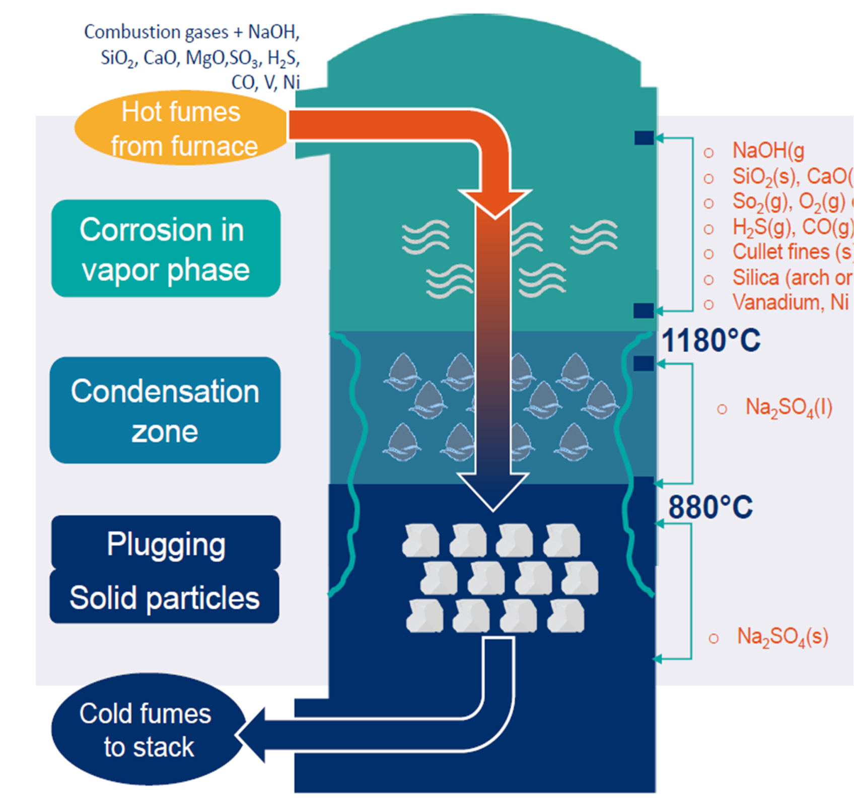
Beyond the corrosion caused to refractory materials, this process will progressively obstruct pathways for the air and fumes, reduce the free cross-sections of the channels, and ultimately decrease the energy efficiency of the regenerators. This will lead to increased fuel consumption in order to maintain the global energy input to the furnace (Figure 5).
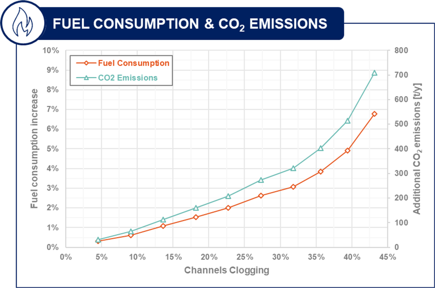
The simulation results obtained using REGEN®, a SEFPRO-proprietary software, highlight that uncontrolled clogging evolution and late cleaning operations can significantly increase energy consumption (Figure 5).
The high corrosion resistance of fused-cast CRUCIFORMS® checkers is a positive factor to withstand clogging-related corrosion induced by the contact with such slags. The high thermal shock resistance of CRUCIFORMS® checkers is also compatible with various cleaning processes used inside regenerator packings as curative maintenance.
SEFPRO GUARD® Monitoring solution
In addition to the CRUCIFORMS® checkers, SEFPRO is now offering a monitoring system able to follow the clogging phenomenon inside the regenerators, through irradiation of the regenerator floor. Ray casting simulations allowed to better understand how thermal radiation phenomena inside the regenerators result in light patterns at the bottom of the chambers (Figure 6).
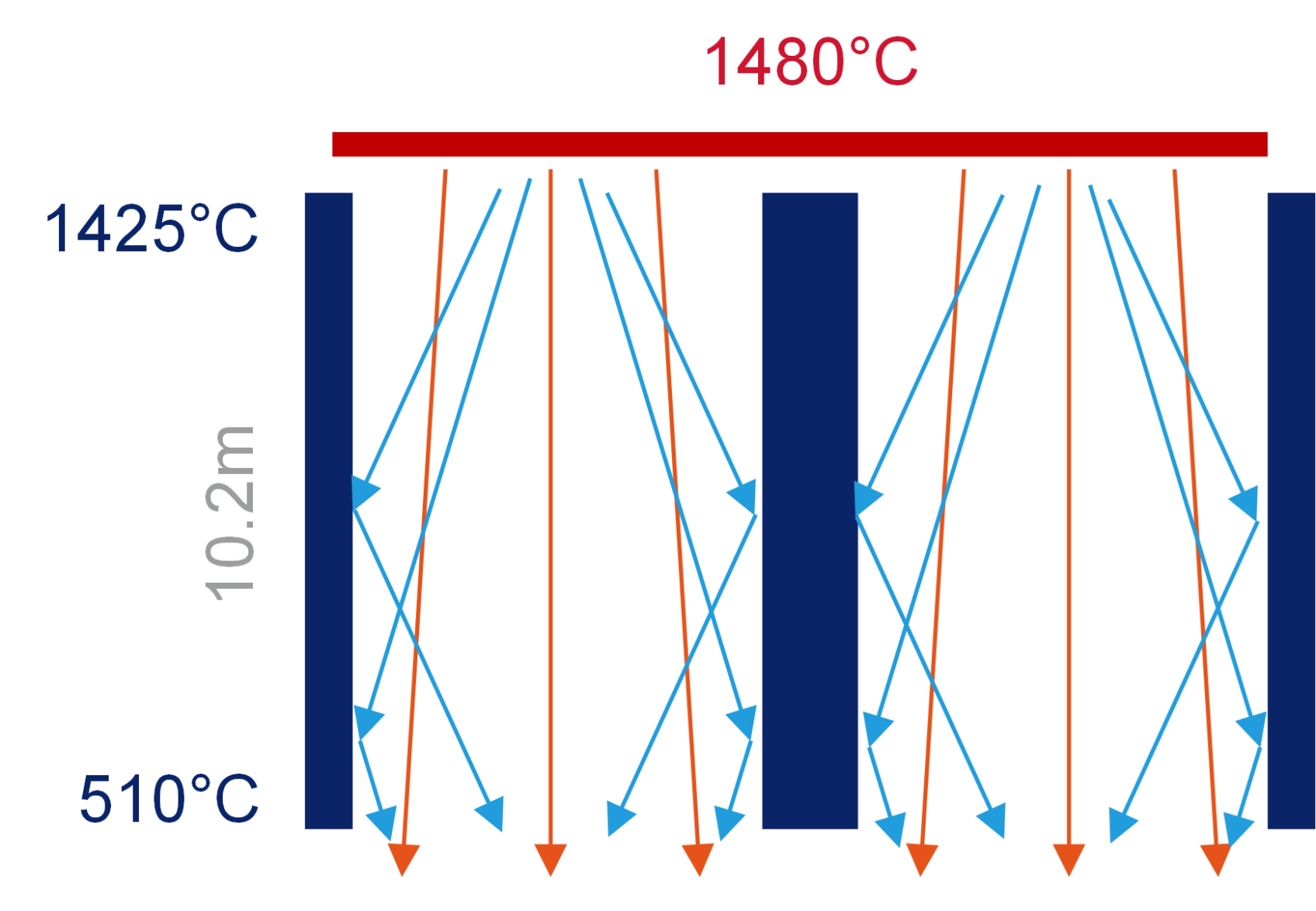
The light patterns on the chamber floor are thus composed of two components (Figure 7):
- A direct component due to non-reflected light emitted from the hot regenerator superstructure,
- A diffuse component due to reflections / emissions off the walls of the channels.
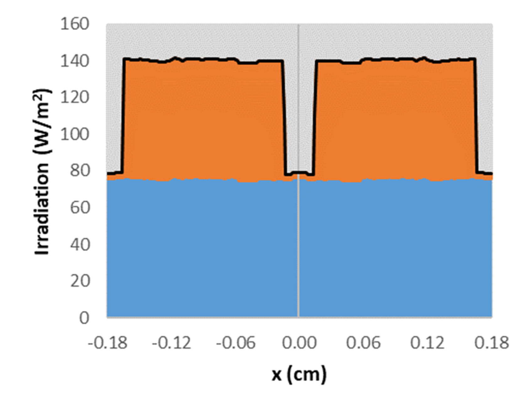
When clogging occurs, the light patterns on the chamber floor (illustrated in Figure 8) significantly change. Both luminous intensity and bright surface area of the patterns decrease, as thermal radiation from the superstructure is progressively prevented from reaching the bottom of the chambers. Simulation results (Figure 9) show that clogging affects both direct and diffuse lighting of the chamber floor.
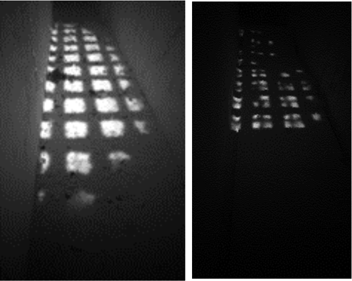
The described phenomenon can be analyzed with the support of image processing and machine learning algorithmThe described phenomenon can be analyzed with the support of image processing and machine learning algorithms, considering radiation energy spectra and the evolution of radiating surfaces throughout the furnace’s campaign (Figure 9).
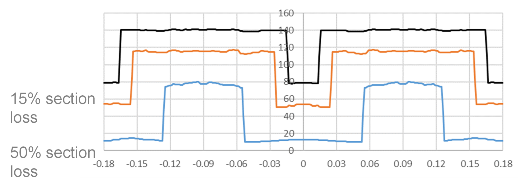
Thanks to the SEFPRO GUARD® Monitoring Solution, it is possible to track changes in the light patterns on a regular basis, and calculate real-time indicators describing the evolution of clogging inside each regenerative chamber. Following the evolution of these clogging indicators with time will allow operational teams to better assess the clogging phenomena of the chambers, prepare preventive maintenance operations, and ultimately maintain the best possible energy efficiency while minimizing fossil fuel consumption.
Anatomy of the SEFPRO GUARD® Regenerator Monitoring System
SEFPRO, with the experience of the application as a provider and designer of the CRUCIFORMS® geometries, together with the ability to estimate the thermal efficiency of the regenerators thanks to the REGEN® simulation software, developed a new computer vision system to help glassmakers assess the chamber clogging evolution.
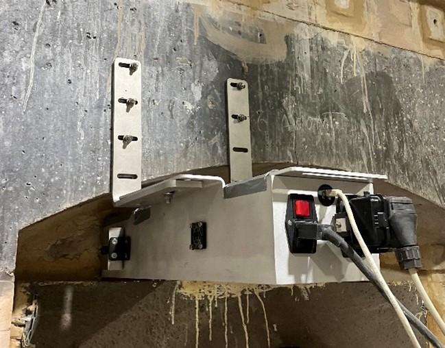
The SEFPRO GUARD® Regenerator Monitoring System is designed to be installed below the rider arches, at the bottom of the regenerators. The installation can be adapted to any furnace thanks to a custom-made design developed to meet the needs of every glassmaker (Figure 10).
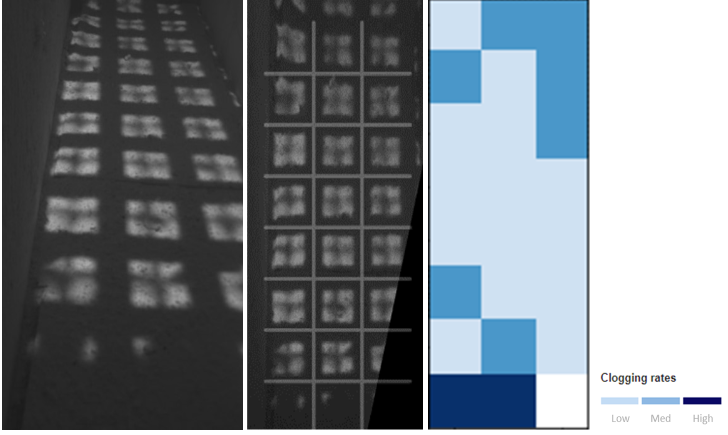
After acquisition on-site, data are transferred to a secure cloud environment, where they are processed with an automatic grid identification and irradiation analysis algorithm (Figure 11).
SEFPRO GUARD® Web Portal
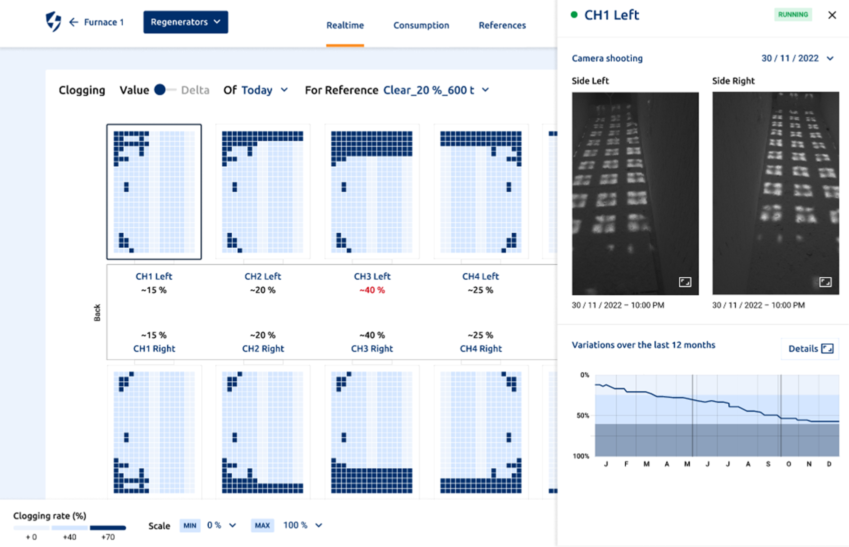
The library of high-definition pictures and indicators that describe the clogging evolution inside the regenerators is stored in a secure environment online, and may be accessed by glassmakers through the SEFPRO GUARD® Web Portal.
Aiming at describing thermal efficiency and/or energy consumption, additional operational data can also be collected by the device. Thanks to machine learning and data analysis algorithms available through the portal, scenarios can be built to provide these new indicators in addition to the clogging evaluation.
By accessing the SEFPRO GUARD® Web Portal, all this information is visible with multiple visualization options, be it pictures, clogging maps and/or curves describing these evolutions throughout the campaign (Figure 12).
Conclusion
With the goal of reducing energy consumption and global carbon emissions, SEFPRO is fully committed to developing smart and innovative real-time monitoring systems to provide an easy, safe, and reliable method to manage glass furnace regenerators.
Thanks to machine learning supported by cloud technology and a web interface, this solution can help glassmakers track the evolution of regenerator clogging. The regular assessment of clogging can be used as a decision-making tool regarding maintenance operations, whether preventive or corrective.
SEFPRO GUARD® Regenerator Monitoring System is an asset for maintaining the highest level of energy efficiency provided by the CRUCIFORMS® solution, and should help glassmakers make the best maintenance decisions, thus limiting operating costs.
Authors
E. Lopez1, ZK Low1, M. Gaubil2, V. Mathieu2, S. Schaller2
1 SGR PROVENCE, 2 SEFPRO
Issued in Glass International-May2024

The glass industry is facing more and more stringent challenges related to carbon emiss...

The glass industry faces a challenge to reduce the environmental footprint of its glass...